Selecting the right WFI distribution system is one of the most critical engineering decisions in any pharmaceutical, biotech, or medical device facility. Since Water for Injection (WFI) is directly tied to product safety and regulatory compliance, even small flaws in distribution design can lead to microbial growth, unstable temperatures, higher energy consumption, or system downtime that impacts production.
For facilities upgrading their utilities or planning for long-term expansion, understanding the engineering principles behind a reliable WFI distribution system is essential. The following guide outlines the core design considerations, practical evaluation points, and industry best practices to help facilities build a system that is efficient, compliant, and future-ready.
Every WFI distribution system should be designed backward—from actual WFI consumption behavior to piping and equipment specifications. The defining factors include:
Peak flow requirements across production lines
Simultaneous user points and their withdrawal profiles
Minimum return flow needed to maintain loop velocity
Production schedule variations (three-shift operation vs. daytime-only)
Future expansion allowance (usually +20–30%)
Overestimating consumption increases capital expense; underestimating it results in unstable loop pressure or temperature fluctuations.
Recommendation:
Build a consumption matrix that includes hourly, daily, and batch-based water usage patterns.
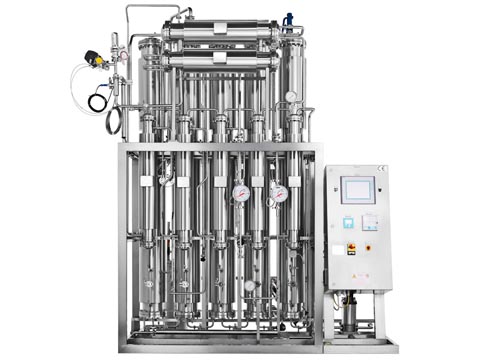
WFI loops typically fall into three main configurations:
| Loop Type | Key Features | When to Use |
|---|---|---|
| Non-pressurized, continuous recirculation | Atmospheric tank, high velocity heating | For facilities with stable demand and moderate loop length |
| Pressurized hot loop | Constant temperature (usually 80–90°C), fully closed | For high sterility assurance and long-distance distribution |
| Cold WFI loop | 2–8°C with ultrafiltration | For specialized bioprocesses requiring low temperatures |
A pressurized hot loop is the industry standard due to its superior microbial control and stable thermal profile. It also supports both large and compact facilities without significant redesign.
Temperature is central to the reliability of a WFI distribution system. Most facilities maintain:
80°C to 90°C in recirculating hot loops
High flow velocity (>1.0–1.5 m/s) to prevent stagnation
Constant turbulence at elbows and risers
Properly insulated piping to reduce heat loss
Microbial risk increases dramatically with even brief drops in temperature or flow rate. Therefore:
Dead legs must remain ≤1.5 D (pipe diameters)
Connections should be minimized
All valves should be sanitary, drainable, and fully swept
If the system must undergo periodic thermal sanitization, verify adequate heat distribution in the most distant points and smallest branch pipes.
Material selection for a WFI distribution system should ensure durability, cleanability, and low contamination risk.
316L stainless steel with δ-ferrite < 0.5%
Electropolished surfaces (0.4–0.6 μm Ra)
Orbital welding with 100% borescope inspection
In recent years, some facilities have explored PP-H or PVDF for cold WFI systems, but stainless steel remains the gold standard for hot loops due to its stability and thermal resistance.
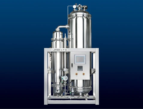
The WFI storage tank is integral to the overall distribution system. A reliable design includes:
Spray ball for continuous internal sanitization
Hydrophobic vent filter to prevent contamination
Slight nitrogen blanketing for atmospheric tanks
Excellent drainability and sloped bottom design
CIP/SIP compatibility
Tank sizing is typically based on:
1–2 hours of peak consumption, plus
Reserve volume for emergency shutdowns
Integrating the storage tank with the loop heater or heat exchanger requires careful temperature control to avoid heat shock or thermal stratification.
Some WFI loops require point-of-use cooling for process equipment or laboratory applications. The heat exchanger must be:
Double-tube or double-plate type
Fully drainable and sanitary
Designed to avoid cross-contamination risks
Biocell’s portfolio includes heat exchanger solutions optimized for hygienic utilities, offering low hold-up volume and rapid cooling performance for WFI applications.
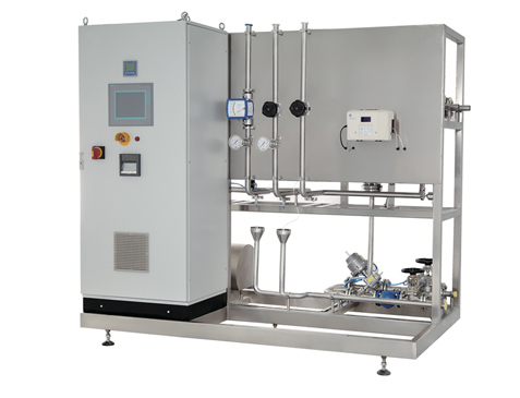
Pumps are the drivers of stability in a WFI distribution system. Performance criteria include:
Constant pressure control with VFD (variable frequency drives)
316L construction and sanitary seals
Low shear design to reduce cavitation risk
Flow control strategies—such as differential pressure control valves or balancing valves—must be validated to maintain minimum loop velocity at all times.
Automation enhances reliability and eliminates human error. A good automation strategy includes:
Continuous monitoring of temperature, pressure, and conductivity
Audit trails that comply with FDA 21 CFR Part 11
Remote diagnostics and alarm notifications
Sanitization cycle automation (thermal or chemical)
Programmable logic controllers (PLCs) should be validated through IQ/OQ/PQ to ensure consistent system performance.
Even the best-designed system becomes unreliable without proper maintainability. Key considerations include:
Easy access to sampling points and valves
Well-located drain points
Clear documentation for traceability
Modular design for component replacement
Defined preventive maintenance intervals for filters, pumps, and heat exchangers
Facilities should maintain detailed life-cycle records to support audits and long-term system reliability.
A well-engineered WFI distribution system supports product quality, regulatory compliance, and operational efficiency. Considering factors such as demand patterns, loop configuration, material selection, microbial control, and automation enables facilities to design systems that are robust and future-proof.
With Biocell’s experience in pharmaceutical water systems and hygienic utilities, facilities can integrate WFI production and distribution solutions that meet the highest industry standards while supporting long-term operational stability.


 English
 日本語
日本語 한국어
한국어 français
 Svenska
 Türkçe
 Malay
Malay Deutsch
 русский